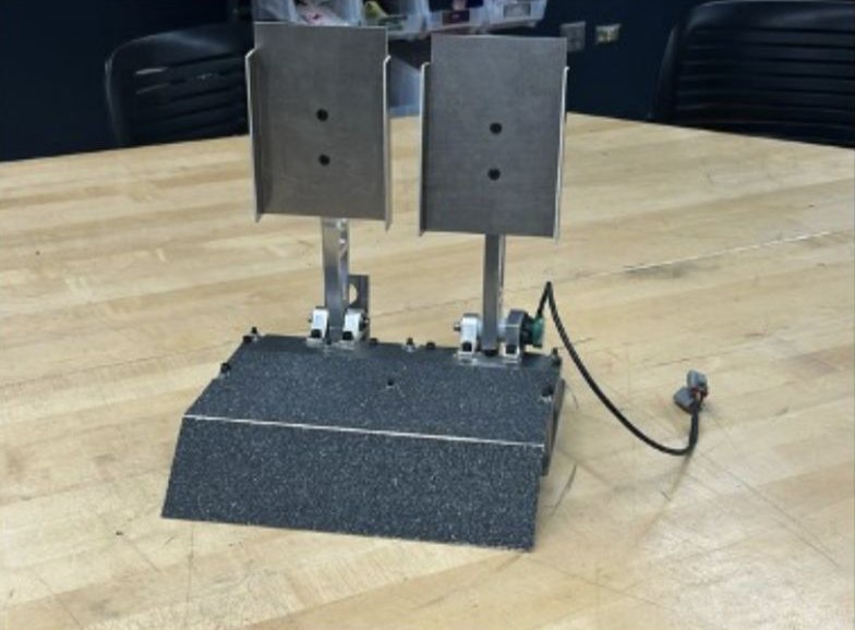
Designed and manufactured the NFR26 pedal box assembly from concept to track-ready hardware.
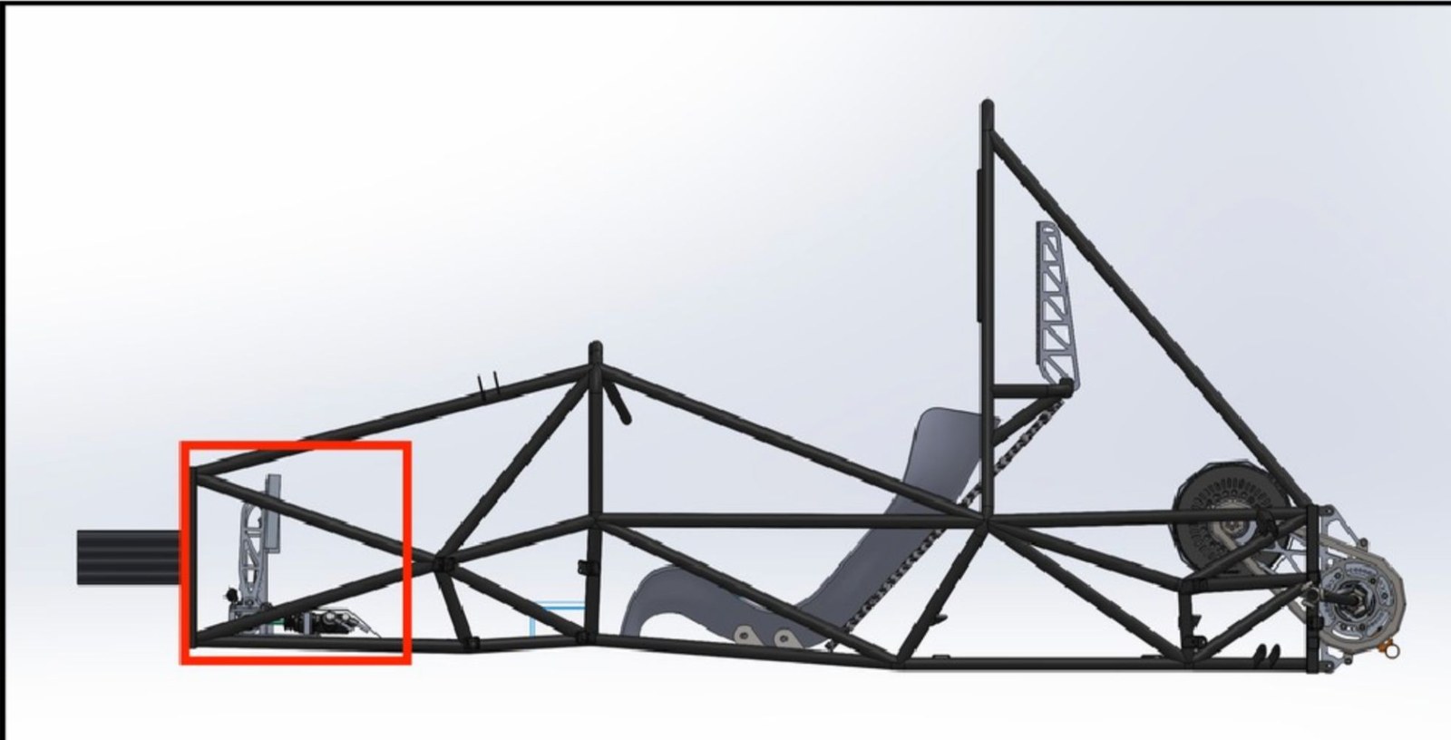
Packaged the driver controls into the chassis: master cylinders, balance bar, reservoirs, sensor mounts and floor interfaces.
Established a clear assembly plan.
How I worked
Modeled the full assembly in SolidWorks to check clearances, pedal travel and fit.
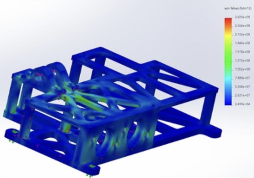
Validated key load cases with FEA on the mounts and the supporting frame.
Organized design decisions and plans into presentations that the team leads discussed and approved.
The challenge
The torsion springs from last year's design were underpowered for the pedal return force this car needed. Torsion springs with enough torque were too large to package inside the assembly.
Spring selection became the constraint. I pivoted the mechanism to linear springs, which meant redesigning the mounting points and other geometry around them.
Results
Strength targets validated in FEA: brake mount factor of safety 3.28, master cylinder mount 2.91, full frame 1.92.
Throttle validated for sensor use: 89° to 66° of pedal angle range, with mechanical stops.
Manufacturing preparations complete, with tool paths created in Fusion 360 CAM.
To add: what the first design looked like, what changed along the way, how many iterations it took, and what you would do differently. Employers want the process and the failures, not just the final part.
Von Mises stress in the FEA model of the pedal boxWhere the pedal box sits in the chassis (outlined in red)